ThimbleKrox
A thimble which, thanks to a GY-521 and an Arduino Micro, can control the mouse pointer.
Introduction
Imagine having the power to control your computer’s mouse pointer with just the subtle movements of your finger. With ThimbleKrox, you can turn this into a reality using simple DIY techniques and readily available components like Arduino Micro and GY-521 sensor. Let’s dive into the journey of creating your very own ThimbleKrox!
Story
The inception of ThimbleKrox dates back to April 9, 2021, when the idea sparked to develop a device capable of mouse pointer control through finger movements.
Since then no further updates have been made but if you want feel free to improve the project
Building Your Own ThimbleKrox
Step 1: Materials and tools needed
Materials needed:
- Arduino Micro or clone (Pay attention that it need to have the ATmega32U4 microcontroller)
- MPU-6050
- Micro USB to USB cable
- Jumper wires
- Elastic band (optional, for hand attachment)
Tools needed:
- Computer with Arduino IDE installed
- Soldering iron (if Arduino pins connectors aren’t pre-assembled)
- 3D printer (optional, for aesthetic purposes)
Step 2: Connection
Connect the Arduino pins to the MPU-6050 pins as follows:
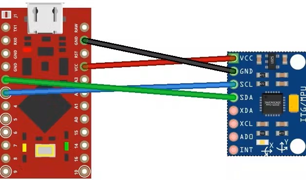
- Arduino VCC to MPU-6050 VCC
- Arduino GND to MPU-6050 GND
- Arduino pin 2 to MPU-6050 SDA
- Arduino pin 3 to MPU-6050 SCL
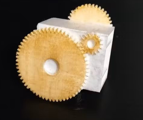
Step 3: Optional 3D Printing
If you want your thimble to look good, and if you have a 3D printer, you can print the physical thimble.
I did it in two versions, one clear which therefore does not require supports to be printed and is not too bulky, and the second one instead that I tried to do in steampunk style without making it too bulky (it is still more bulky than the clear one ), but this one requires supports to be printed and only return best if colored (for PLA I got along well with tempera). Both require to be printed with the part with the two internal protrusions in the bottom
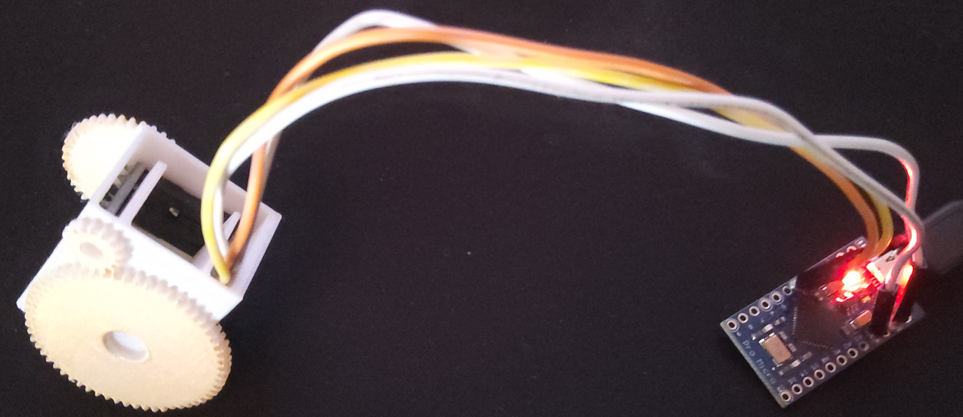
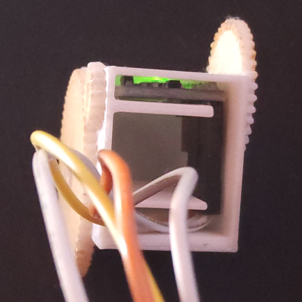
Step 4: Assembly
-
With 3D Printed Thimble: Insert the MPU-6050 into the upper cavity of the thimble, ensuring cables are housed in the lower cavity.
-
Without 3D Printed Thimble: Position the MPU-6050 on the last phalanx of the finger and secure it with adhesive tape or an elastic band.
Step 5: Code and Calibration
Install Required Libraries
Before proceeding with calibration, ensure you have installed the necessary libraries:
Calibrate the ThimleKrox
-
Load the Calibration Code: Begin by loading the ThimbleKrox calibration code onto your Arduino Micro. With the thimble worn, connect the Arduino to your computer and open the Arduino IDE. Upload the calibration sketch to the Arduino.
-
Serial Monitor Setup: Once uploaded, open the serial monitor (Ctrl + Shift + M). You should see data streams displaying values such as gyroscope (gx, gy, gz) and accelerometer (ax, ay, az) readings.
-
Understand Calibration Parameters: The calibration process involves adjusting numerical values in the code to ensure accurate tracking of finger movements. When the ThimbleKrox is tilted in a specific direction, corresponding values for gyroscope and accelerometer readings are observed. These values need to be mapped to the desired mouse movement direction.
-
Interpreting Serial Monitor Output: As you tilt your finger, note the direction indicated in the serial monitor output (e.g., “left”, “right”, “up”, “down”). These directions correspond to the intended movement of the mouse pointer.
-
Adjust Calibration Values: In the calibration code, locate the lines marked with “// calibration line”. These lines determine the threshold values for triggering mouse movements based on sensor readings. Adjust these numerical values iteratively until the desired mouse movement direction matches the finger tilt direction observed in the serial monitor.
For example:
if (ax >= 5000) {                         // calibration line
    right();
}
In this snippet, the condition
ax >= 5000triggers a right mouse movement when the accelerometer reading along the x-axis exceeds 5000. Adjust this threshold value as needed to fine-tune the calibration. -
Upload Updated Calibration Code: After making adjustments, upload the modified calibration code to the Arduino. Repeat the process until all movement directions are accurately calibrated.
-
Sync Calibration with Main Code: Once the calibration version of the thimble is functional, ensure that the values in the main code match those in the calibration code. This synchronization ensures consistency between calibration and actual mouse movement behavior.
-
Upload Main Code: After aligning the calibration parameters, upload the main ThimbleKrox code to the Arduino. Your ThimbleKrox is now calibrated and ready for use!
Step 6: Finish the project
Wear your ThimbleKrox and enjoy seamless control over your computer’s mouse pointer with just the tip of your finger!